12 min to read
Building a Toon Shader in Unity
My voyage into the shader pipeline with Unity
This marks my first step into developing my skills with Unity URP and shader graphics. I’ll be highlighting some of the techniques I’ve learned here.
An Preface into the Graphics Rendering Pipeline
A couple resources that greatly expanded my understanding:
From these resources, I present the following simplified model of how modern GPU’s work:
\[\text{Vertex Data} \rightarrow \text{Vertex Shader} \rightarrow \text{(Geometry Shader)} \rightarrow \text{Primitive Setup/Rasterization} \rightarrow \text{Fragment Shader} \rightarrow \text{Blending} \rightarrow \text{Output}\]- Vertex Shader: Takes in vertices and constructs edges, triangles, and other primitives to be used by the fragment shader, which will do math and calculate the color to display per pixel.
- Geometry Shader: Processes entire primitives and is not limited in output, but also typically expensive to use.
- Fragment Shader: Generates colors per fragment (pixel).
With this information, I began diving into constructing my first shader.
First Steps: A Simple Toon Shader
I took a course that worked with 2D graphics and covered a lot of core topics in Computer Graphics, but I wanted to work with 3D Graphics to expand upon those skills I learned. I’ve always adored animation and comics, so I took to the internet to provide me the resources I needed.
I started with Freya Holmes’ Intro to Shaders video on YouTube, which helped me understand most of the basics of writing shaders purely through shader code in Unity. I highly recommend anyone starting out with shaders or graphics in general to give it a quick look.
Of particular help was a Unity blog post, Custom Lighting in Shader Graph, which got me started down this track of non-photorealistic rendering.
The General Idea
From what I’ve learned, I like to think of shaders as blackboxes that take inputs in the form of properties, do lots of math and calculations upon those inputs, and then output a final color to display on your screen. The inputs into the shaders can be in the form of lighting characteristics, colors, UV properties, texture maps, etc., but typically the output is focused on the color at each pixel on the screen.
In my graphics course, we went through many low-level optimizations to improve the runtime at which these calculations are done, but now I’m looking to focus more on the content of the calculations done in shaders.
The Art Direction
I want to focus on a comic-book inspired art style shader that looks like something out of Spider-verse. To do this, we should follow the steps sketch and comic book artists take when making drawings, and convert that pipeline to our shader in Unity. Luckily, with the help of Shader Graph, there isn’t as much code necessary to create a basic toon shader in Unity.
Constructing advanced effects involves combining several substeps that are easier to understand. In Shader Graph, the idea of abstraction becomes highly relevant as substeps can be converted to subgraphs. For a toon shader, I will outline these “substeps” in stages.

Basic Lambert (Diffuse) Lighting
A quick note! The basic lighting model uses:
surfaceColor = emissive + ambient + diffuse + specular
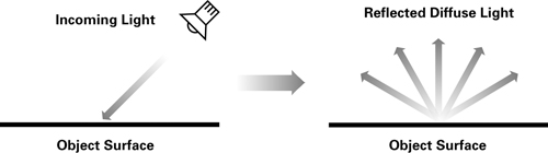
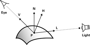
Diffuse lighting is the result of directed light reflecting off a surface equally in all directions. The Lambertian reflectance model provides a simple mathematical equation to calculate diffuse lighting. As a surface is tilted away from perpendicular to the light, its reflection decreases. Given a vector B and its unit direction B’, the dot product of any vector A with B’ provides the projection of A onto B. Essentially, the dot product allows us to determine the parallelism of two vectors with each other.
Using these principles we obtain the following equation:
\[K_{d} = L \cdot N \times C \times I_{L}\]Where $L$ is the normalized light direction vector, $N$ is the unit normal vector of the surface, $C$ is the color of the light, and $I_{L}$ is the intensity of the light source.
Intensity in Real Life
Unfortunately, intensity levels are not constrained between 0 and 1 in real life. In an outdoor environnment, they easily exceed the ideal levels we like to use in Computer Graphics. To solve this problem for photorealistic applications, lighting is often rendered in High Dynamic Range (HDR) or uses Tone Mapping to address the issues of exceeding intensities. In our case, we clamp the result of the dot product $N \cdot L$ between 0 and 1.
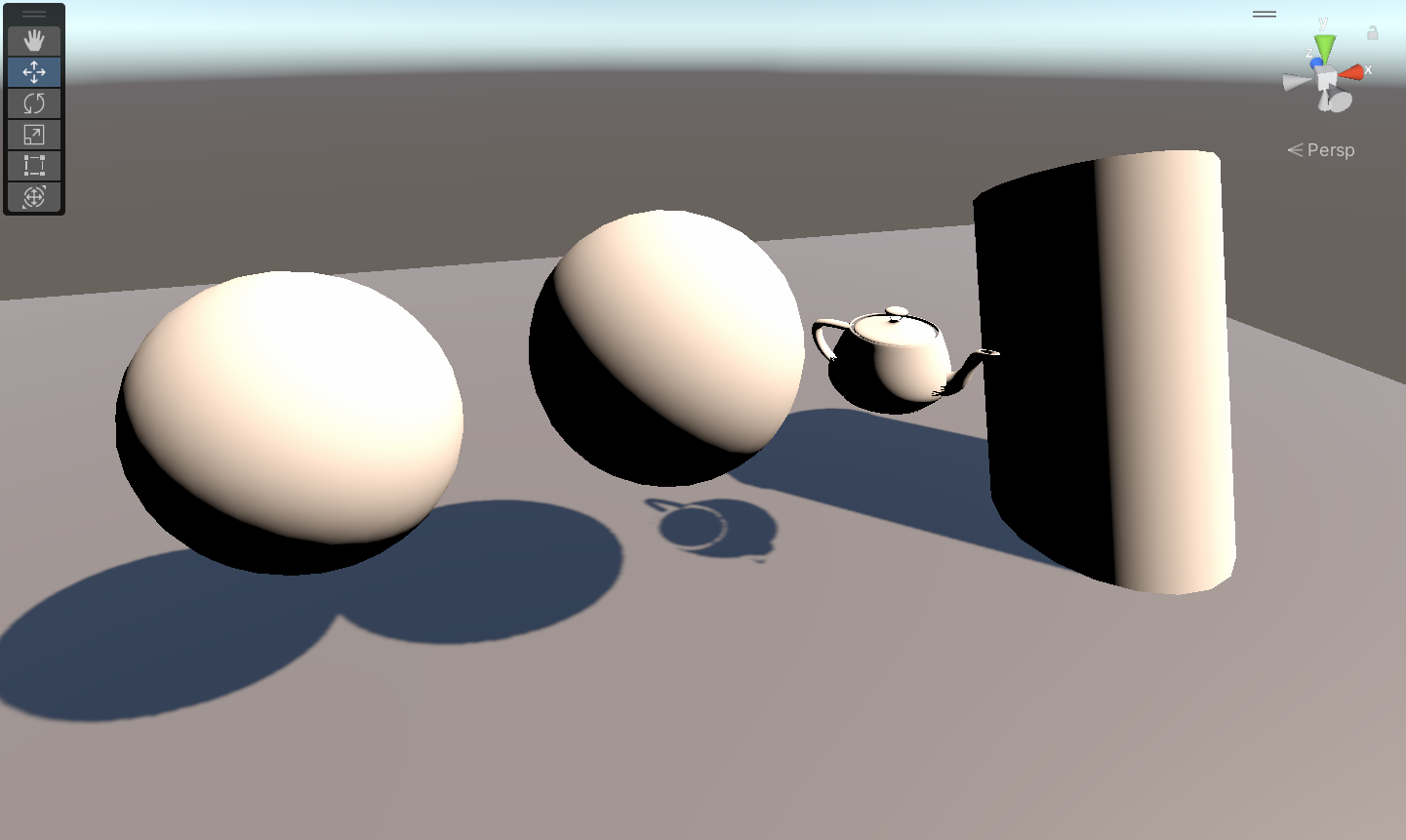
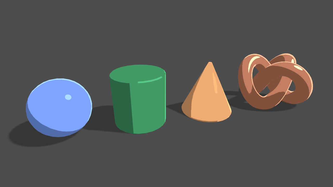
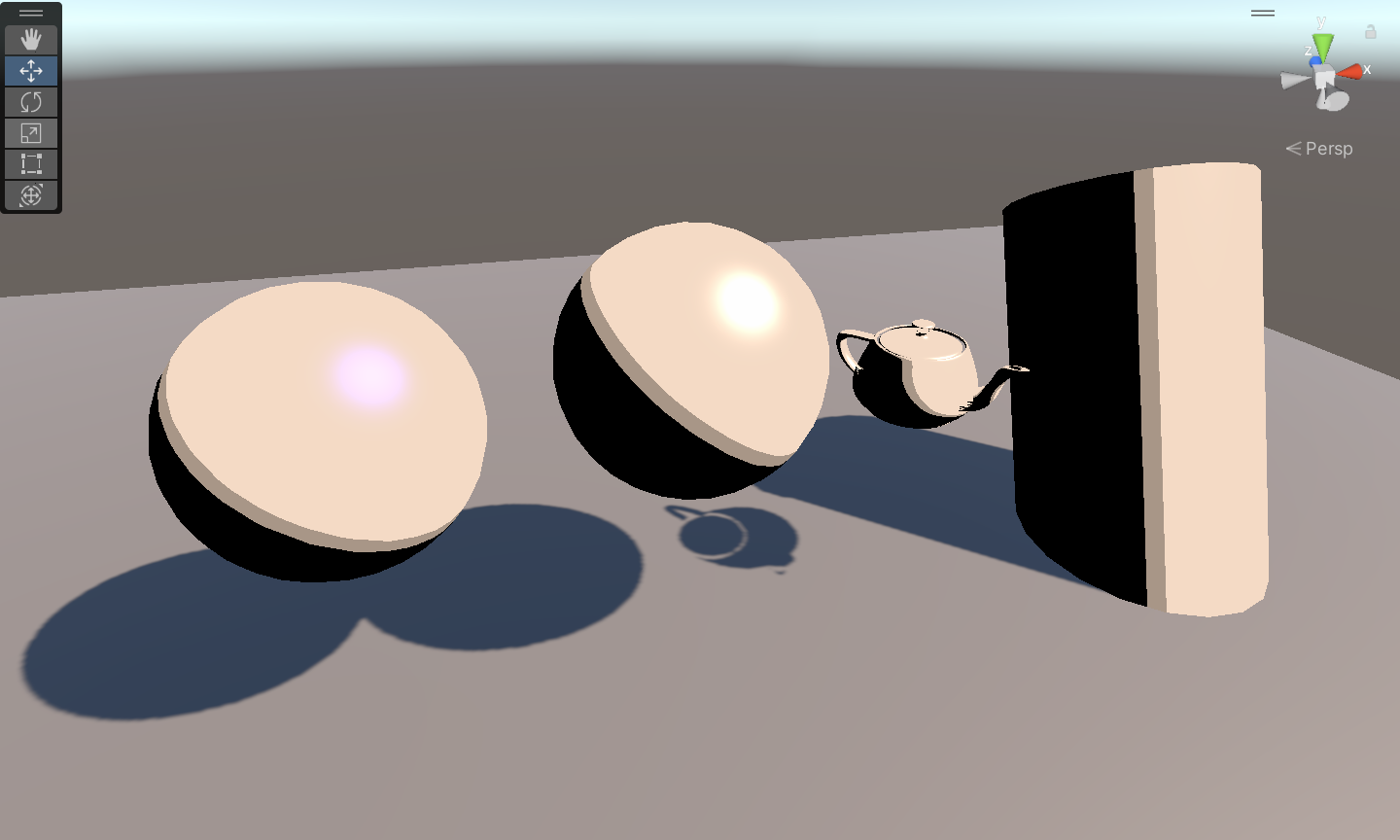
I’ll be using some basic shapes, along with the Utah Teapot, to test my shader and its evolution.
Specular Lighting
The Phong model is superceded by the Blinn-Phong model, an approximation that proves to be better in many cases, but the basic Phong model is also suitable, and describes surface light as the combination of ambient, diffuse, and specular lighting. Specular Lighting, or specular reflection, is the mirror-like reflection of light on a surface. This type of lighting relies on vectors pointing towards the viewer, or in our case, the camera.
In HLSL, this looks like the following:
Smoothness = exp2(10 * Smoothness + 1);
WorldNormal = normalize(WorldNormal);
WorldView = SafeNormalize(WorldView);
Out = LightingSpecular(Color, Direction, WorldNormal, WorldView, half4(Specular, 0), Smoothness);
Here, the user has defined the specular light in the input Specular, and the LightingSpecular function executes the following equation:
where $C$ is the light color, $N$ is the unit normal vector, $H$ is the unit halfway vector between the view direction and the light direction, and $smoothness$ defines how shiny a surface is. Note that we also clamp the term $N \cdot H$ here.

The lighting might be hard to see here, but it usually appears as the bright white dots or lines that are directed towards the light source. Once we begin clamping intensity values in the toonifying part, they should be easier to see.
Ambient and Emissive Lighting
Ambient light is the light scattered from around the environment onto our surface. In Shader Graph, this is handled by Global Illumination values that are baked onto the surface of an object. The exact implementation is different per render pipeline.
Emissive light is the light given off by the object, e.g. “glowing” from the object. For our purposes, we won’t consider this for now, but I might look into some interesting cases of emissive light in the future.
Now that we have some basic lighting down, let’s get to the fun part: toonifying!
Next Steps: Toonifying
Let’s get started with the toon part!
Firstly, a large part of achieving a non-photo realistic look is restricting the number of colors in our palette - this is called Cel shading. A super easy implementation of cel shading is to floor, ceiling, or round intensity values from the light source (the only difference is a shift in where shading begins), and then use a step function to find the appropriate color to match the intensity with.
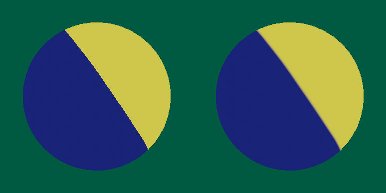
Using a step/smoothstep function for Cel Shading
Credit: Panthavma
Ramp Lighting / Inking
Another method we could use is ramp lighting, which relies on a ramp, or a 1D texture that matches a light intensity to a color ramp. In this way, we can specify what colors we want our shadows to be, and have greater control over the colors within the light falloff.
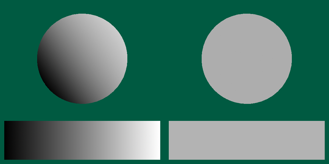

Ramp Lighting in Action
Credit: Panthavma
In Unity with Shader Graph, the effect can be achieved by:
- Converting RGBA (red, green, blue, alpha) -> HSV (hue, saturation, value), where value is the measure of light intensity. Note that when using the Split node in Shader Graph, V is mapped to an output of B.
- The value is inputted into the ramp, in the form of a simple gradient, where the artist/user can specify the color scheme for the shader.
- Finally, we reconvert the HSV -> RGB and use the output as our color.
You can now easily see the color palette chosen by sampling from using ramp lighting.
Crosshatching
Ooooo, this is a tough one. A simple cross hatch is easy to achieve, but the problem is that crosshatching is very intentional when sketching and drawing. Achieving realistic crosshatching is likely very costly, and might still require human input, however there are algorithms out there that attempt more realistic crosshatching. From what I’ve seen from most toon shaders, they either neglect the entire prospect of crosshatching, or use a relatively simple implementation to achieve a desired look. In fact, observing the Spiderverse movies themselves, I found that the hatching mainly flows in a single direction. For more realistic strokes and inklines, the creators used Machine Learning (and Blender!) to reproduce a handdrawn look. Cool!
Many of the basic tutorials you will find on crosshatching suggest using a texture with UV mapping to draw patterns onto the object itself based on lighting conditions, however I would suggest against doing this personally, because I don’t think it looks as good. Instead, one could use a procedural method of generating patterns, using nodes or functions already present in Shader Graph and HLSL, and applying those patterns to the Toon Ramps mentioned in the previous section, so that we target similar regions of darkness for crosshatching. I think its also nice to add some user exposed properties here to control the exact look of hatching for the shader.
I used a stripes pattern angled based on the view position, and created another stripes instance perpendicular, then played around with gradient settings such that there was a slight mismatch in where each direction would appear. I think this is an artistic choice and could be modified for different use cases.
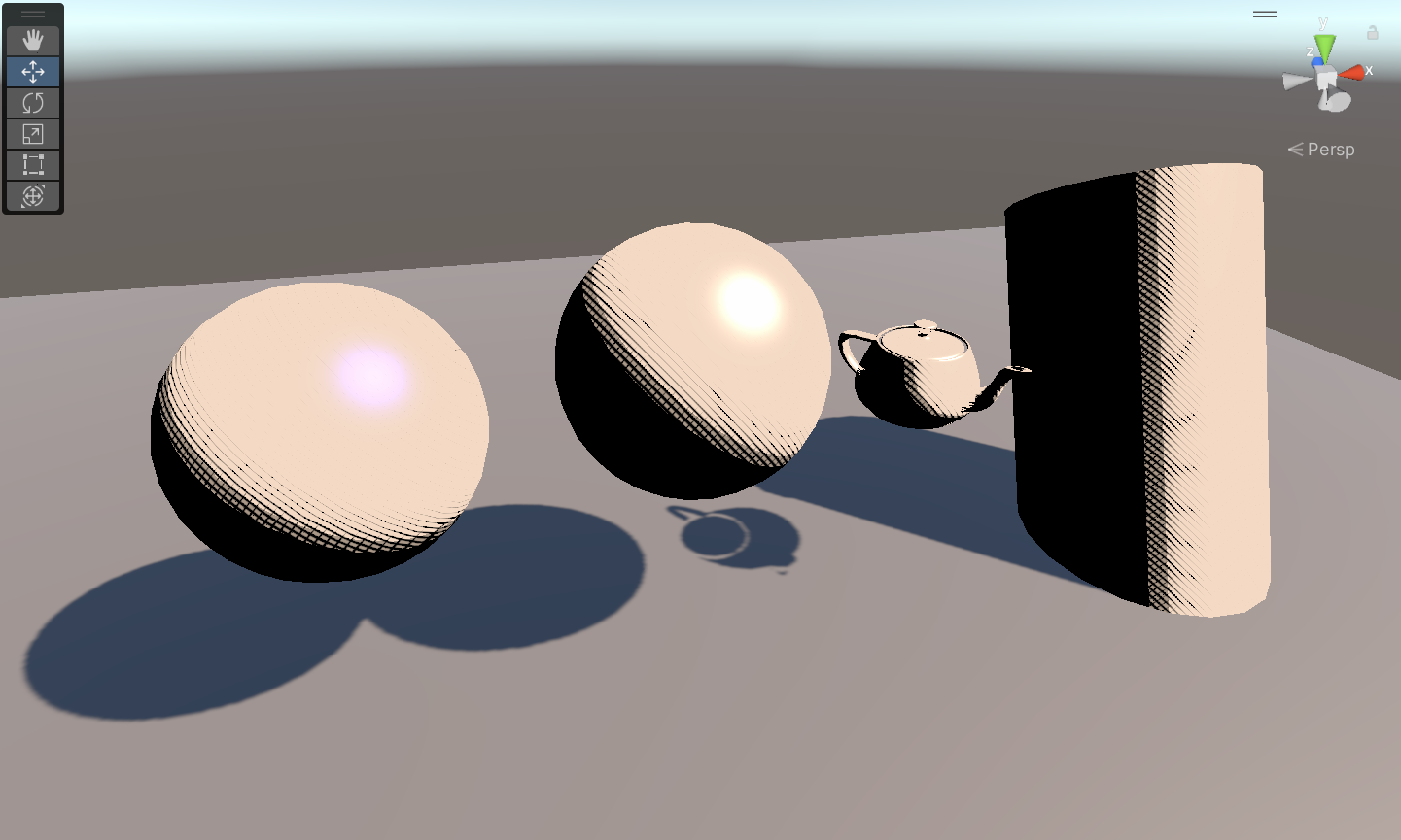
The crosshatch frequency controls the number of lines that appear in the shadow of the object.
Outlines
I used an inverted hull method to implement outlines for my toon shader. I thought this was the simplest method to create outlines, because of its intuitive nature, however, there is a separate method that uses more math with normals to produce outlines, and is generally a more robust method for drawing toon-like outlines. In Shader Graph, we use front face culling to generate an extruded outline shape so that only the outline is drawn, rather than the object itself, taking normals and positions in object space and adding them to get the outline. The result is also scaled by thickness and multiplied by color properties to provide more control over the desired effect.

Outlines made using the inverted hull method. These outlines do not draw properly under certain positioning conditions, something I’d want to explore more in the future.
Stippling
Stippling is a technique used to mimic effects of shading by patterning of small dots on the screen. In many ways, the process of creating stippling patterns is similar to cross hatching, but for reflective specular lighting rather than shadows. As such, we can ramp light the specular light outputted from the shader, then apply a procedurrally created pattern of dots to create the desired effect.
Specular Lighting + Stippling! We are almost done with the toon shader.
Rim Lighting
The final effect of our toon shader, rim lighting, has to do with the bright reflective light on the edges of surfaces and objects when viewed at different angles. Rim lighting is described by the Fresnel equations, since in rim lighting, light hits objects at near-grazing angles, or angles of incidence near 90 degrees to the light source. The Fresnel equations characterize how reflectivity of light increases as the angle of incidence approaches the grazing angle.
A simple math equation to represent Fresnel Lighting is as follows: \(K_{f} = (1 - \text{saturate}(N \cdot V))^{power}\)
Here, you can see how the lighting increases as the angle between $N$ and $V$ widens.
I’m not sure of the exact implementation of Fresnel Lighting in Shader Graph, but I assume it is something along the line’s of Schlick’s approximation

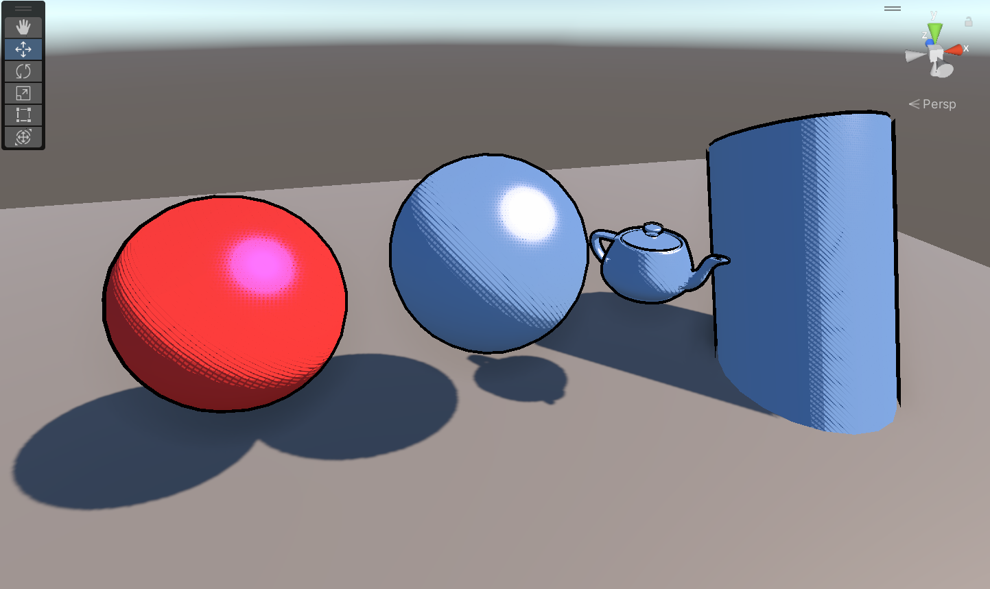
And here’s the final effect!
Conclusions
I had a great time working with toon lighting and toon shaders, and this process has inspired me to continue working on improving my programming abilities and graphics understanding. I didn’t have to code too much in this project, but I’m hoping to code more on whatever I decide to work on next.
There are also a few topics I’d like to revisit later. For example, the method for generating outlines is not as robust as I’d like it to be, and I think I would spend some time creating a more precise model for generating outlines using Depth Normals. Also, I want to improve or modify the crosshatching technique to create more sketchlike hatches, instead of the perfect 45 degree aligned hatches that are found in my shader right now.
Future Work
So, that’s it for now! I have a huge list of topics I want to visit and explore next, and also improve on the toon shader. Here’s a short list of some topics I want to get into:
- Dithering
- Custom Renderers
- Photorealistic Shaders
- Raytracing
- Vector Colors
- More UV Maps and Textures
- Edge Detection with Sobel
- Chromatic Aberration
- Anti-Aliasing
- Streamline Hatching
- and more…
Thanks for reading!